 Proudly Made in the USA
  800.269.1462

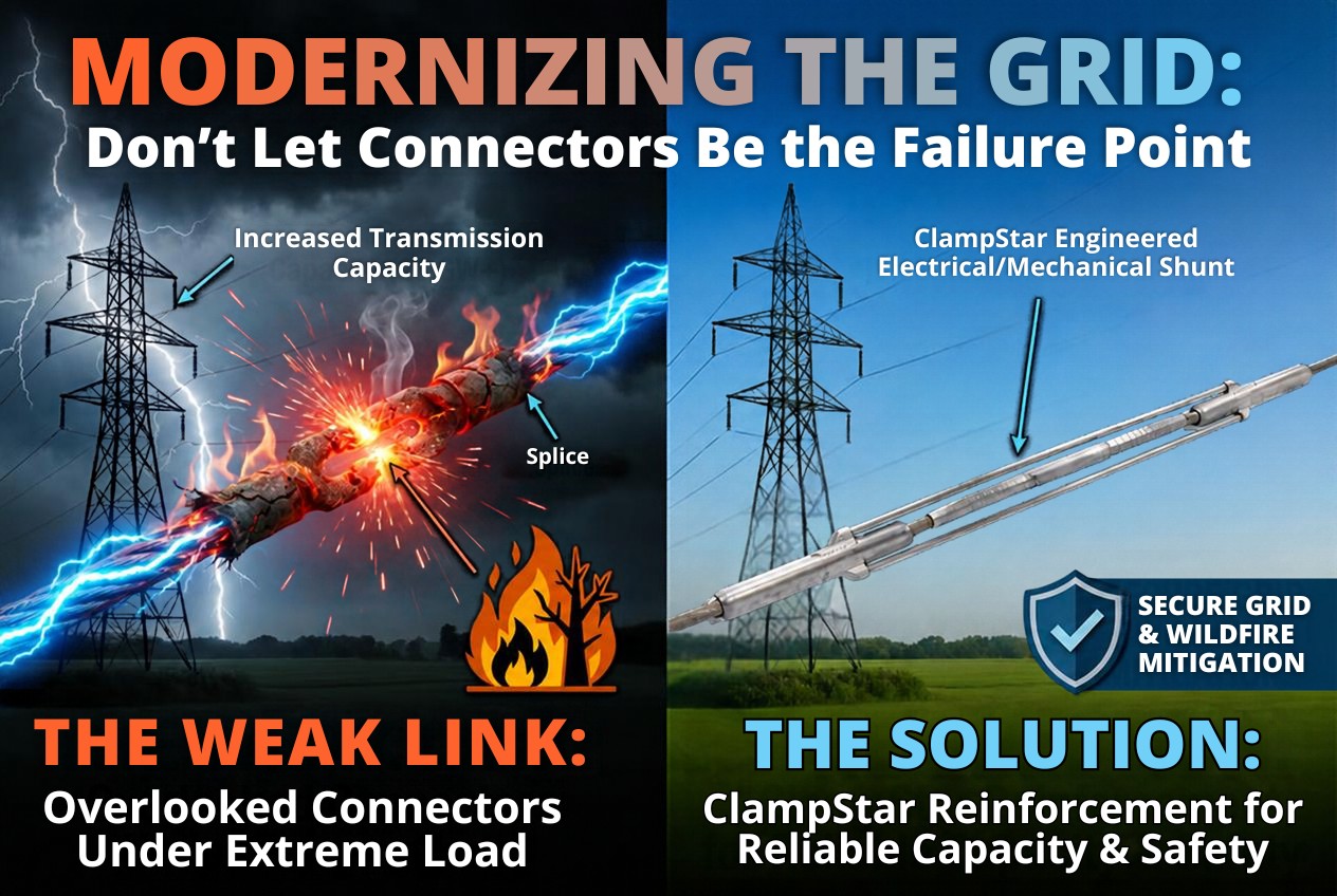
More Current. Old Connections. 21,000 Miles at Risk
DOE just selected 31 projects expected to unlock more than 23 GW from existing transmission infrastructure. Every ampere behind those gigawatts still has to pass through a splice, a dead end, or another connection point.
We recently asked a question about DOE's SPARK program: With $1.9 billion in federal transmission investment on the table, has anyone qualified the connectors?
On September 24, DOE provided clarity on the $1.9 billion investment, but not on the connection point. The Office of Electricity announced 31 projects across 26 states, totaling $5.25 billion: $1.9 billion in federal funding and $3.35 billion in recipient cost share. The projects are expected to reconductor or rebuild more than 1,500 miles of transmission lines while deploying grid-enhancing technologies across nearly 21,000 miles. DOE estimates this will add more than 23 GW of capacity and says the approach will bypass the multi-decade timelines typically required to build entirely new transmission corridors. The premise is sound. Increasing the capacity of existing corridors avoids much of the right-of-way and construction time that new lines require.
The SPARK selections reach far beyond the lines being rebuilt. For every mile of transmission line reconductored or rebuilt, roughly 14 more miles will gain capacity through grid-enhancing technologies (GETs). Across nearly 21,000 miles of existing lines, recipients are expected to deploy advanced line rating systems, power flow controls, and sensors to get more out of existing infrastructure.
This technology fundamentally alters the grid's duty cycle. It changes how heavily a line can be loaded, pushing more current through existing conductors. This adds significant thermal and mechanical duty onto all existing connectors, most of which have not been upgraded to handle the increased load.
This distinction matters. A reconductoring project generally replaces the connectors along with the conductor, though usually with the same compression technology. A GETs project typically leaves the existing connectors in place while asking them to carry more. By optimizing the 21,000 miles without reinforcing the physical connection points, we have not built a resilient grid. We have simply engineered a massive network of unmitigated weak links.
Much of today's reconductoring discussion centers on newer conductor designs. But ACSS is hardly new. As Paul Springer of Springer Power Consulting writes, "ACSS is the original high-temperature low-sag (HTLS) conductor." It remains an important option for high-temperature reconductoring, with a maximum continuous operating temperature (MCOT) of 250°C.
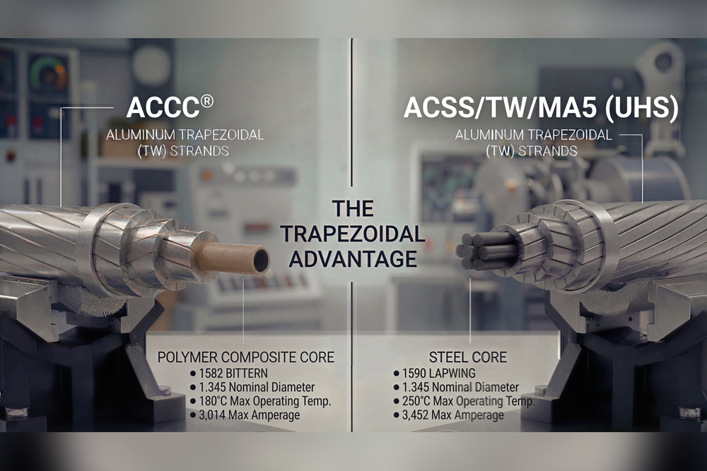
Springer's like-for-like assessment puts numbers around the choice. Composite core conductors offer real advantages in applications involving very long spans and severe clearance constraints. But in his reconductoring case, an ACSS/TW/MA5 conductor operated at its 250°C thermal rating, with modest structure modifications, delivered 1,990 A, 17% more than the maximum capacity of the composite core alternative evaluated. Steel core also has a substantially higher elastic modulus than composite core, and under heavy ice, the best steel core option sagged 2.3 feet less than the best composite core option. And as Springer notes, a composite core does not itself carry current.
The point is not that one conductor technology wins every application. Manufacturers rate conventional ACSR for 75°C continuous operation. Composite core conductors carry a maximum continuous operating temperature (MCOT) of 180°C. ACSS carries an MCOT of 250°C, and no rating exists above it. Utilities seldom run a line at its MCOT for long, because line losses rise steeply with temperature. The value of a high MCOT is the thermal headroom available for the relatively few hours when the grid needs it most, and ACSS provides the vital increased capacity to absorb critical grid contingencies. Those hours include contingencies, the condition planners call N-1, formalized in NERC Reliability Standard TPL-001-5.1 as planning event P1. When a parallel circuit is lost, the surviving line can be called on to carry roughly double the current, and that means four times the I²R heating at every splice and dead end.
The conductor's thermal capability does not, by itself, establish the capability of the complete conductor-and-connector system. Along every line, current and mechanical load eventually reach a connection point, and each connection point fails in its own way. This paper works through the connection points one connection type at a time.
What actually holds a conductor together?
Compression splices and dead ends have no fasteners. Their mechanical grip and their electrical contact both depend on the residual clamping force left in the sleeve after the crimping dies are removed.
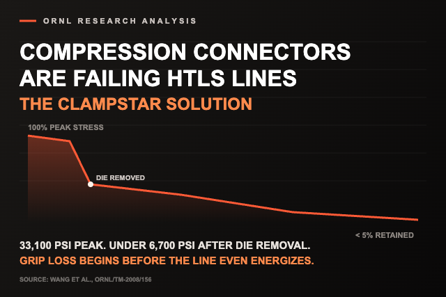
Research at Oak Ridge National Laboratory, sponsored jointly by DOE and EPRI, quantified how much of that force survives. During crimping, compressive stress at the sleeve-to-conductor interface reaches roughly 33,100 to 37,100 psi. Once the dies come off and the sleeve springs back elastically, it falls to 1,700 to 6,700 psi, only 5.13% to 18.05% of the peak. ORNL's simulations of the same splice under tension and thermal cycling then showed a further 92 to 95% reduction once cycling reached 100 to 125°C, temperatures high-temperature conductors reach in ordinary, non-emergency service.
ORNL's work used conventional ACSR with hard-drawn aluminum strands. ACSS uses fully annealed aluminum, which deforms and flows under compression rather than locking firmly within the sleeve, so a compression connector on ACSS starts with less residual clamping force. Thermal cycling further reduces that force over time. A line that normally runs cool but is pushed harder during peaks and contingency events can accumulate these cycles, the very operating pattern enabled by dynamic line rating and other grid-enhancing technologies.
Installation decides the starting point
A compression connector's performance depends heavily on a single step performed before the sleeve is crimped, and one that leaves no evidence once it is: wire-brushing the conductor to remove the aluminum oxide layer.
That step, along with applying inhibitor, is prescribed for virtually every connector installed on aluminum conductor. CIGRE Technical Brochure 905 documents what happens when those steps are skipped on compression fittings: the connector can overheat, distort, and allow moisture and corrosive pollutants in. The brochure attributes many compression fitting failures to inadequate surface preparation. Traditional mineral-oil-based inhibitor compounds also break down at about 162°C, well within the operating range of high-temperature conductors.
Furthermore, standard diagnostic measurements fall short of providing a complete answer. According to CIGRE Technical Brochure 905, neither resistance testing nor infrared thermography can identify hidden flaws that leave electrical resistance largely unaltered, such as a severed steel core or a misaligned sleeve. A spotless infrared scan merely reflects conditions at a single instant; it offers no guarantee regarding performance during the next demand peak.
That raises an uncomfortable qualification question. Industry mechanical qualification tests are performed on new connectors. A connector that passes its initial tensile test has shown it can hold the required load when new, not after years of high-temperature operation. EPRI's research reinforces this concern: above 100°C, hard-drawn aluminum strands lose tensile strength over time, faster as temperature rises, and EPRI notes knowledge gaps in the long-term performance and inspection of advanced conductors and "their associated hardware." Connector heating follows I²R, so a 30% increase in current raises the heat generated at a given resistance by about 69%. The question is whether the connectors can carry that added duty.
1. The splice: set on installation day, weakened every hot hour after
Field data shows the consequences. Avista's reliability modeling of 450 full-tension splices on its 230-kV system predicted that about 4% were in very poor condition and likely to fail within ten years, with another 25% questionable. Infrared inspections following earlier splice failures had not been able to predict which splices would fail next, so crews tested about 350 of those splices from a helicopter with a resistance-measuring instrument. One in five measured at least 1.5 times the conductor's resistance at the splice connection, and the worst read 31 times the conductor's resistance.
A large investor-owned utility X-rayed approximately 70 transmission compression splices and found that roughly 80% had not been installed correctly. Compression splicing uses the same connectors, dies, and procedures industry-wide, often with the same contractors, so any utility X-raying its own splices would likely find similar results.
2. The dead end: tension and current meet at the structure
A dead end does two jobs at once. Mechanically, it transfers the conductor's full tension into the structure. Electrically, it carries the full line current: from the conductor strands, across the compressed interface, through the body of the dead end and out its terminal pad to the jumper. In a compression dead end, both jobs pass through the same compressed section of the sleeve, and both depend on the residual clamping force described above.
That shared dependence is what makes a failing dead end difficult to contain. As clamping force relaxes, contact resistance in the compressed section rises, and so does the heat generated there. Heat accelerates internal corrosion, which further raises resistance. CIGRE TB 905 documents where that cycle can end: a compression dead-end terminal pad that separated from the conductor after internal corrosion and high resistance in the compressed section caused it to overheat. A dead end that runs hot is no longer just a hot spot. It is a failing grip on the conductor, and when that grip fails, an energized conductor drops onto whatever lies below: a road, a field, a neighborhood, or dry brush in fire season.
3. The suspension clamp: the support point no one rates
The suspension clamp is the connection point that capacity studies are least likely to mention. Its case is mechanical, not electrical. At every tangent structure, the clamp holds the conductor's weight where the conductor bends, vibrates, and wears, and the industry knows less about that point than it should:
- Fatigue concentrates there. CIGRE TB 905 explains that cyclic conductor motion causes fretting fatigue of the strands where movement is restrained, mostly at suspension clamps. X-ray inspection has found broken aluminum strands inside suspension clamps.
- The data stops at conventional conductors. Safe vibration limits are available mainly for ACSR in metal-to-metal clamps. CIGRE TB 905 calls for more endurance data on conductors with annealed aluminum and trapezoidal strands, such as ACSS, the original HTLS conductor, and on clamps with elastomer inserts. The brochure itself is limited to ACSR, AAAC, and AACSR operating at no more than 95°C, and does not cover high-temperature, low-sag conductors.
In 2003, National Grid engineers wrote that high-temperature conductors require "special suspension clamps, high-temperature deadends, and high-temperature splices." Twenty-three years later, dynamic line rating makes that warning more relevant, not less. A line cleared to carry more current is not automatically a line whose existing connection points are qualified for the duty that comes with it.
Two standards, two very different questions
ANSI C119.4 is the industry's established connector standard, scoped for connectors designed for normal operation at or below 93°C. It also does not require any mechanical tension on the conductor during thermal cycling. A splice or dead end can pass C119.4 in the lab without carrying any of the tension it will hold every day in the air.
ANSI C119.7 is written specifically for connectors intended for normal operation above 93°C. EPRI's Advanced Conductor Specification Guide identifies C119.7 for this application and notes that, until it is released, C119.4 and C119.0 should be applied with additional considerations above 93°C. The draft C119.7 protocol cycles the connector at high temperature while holding the conductor under sustained tension, so heat and load act on the connection together, as they do in service. That combination is what wears down the residual clamping force, and C119.4 never tests for it.
C119.7 remains unpublished. Manufacturers publish their own ratings above 93°C, but each rests on their own test protocol. So for any SPARK project, the qualification question comes down to four parts: which protocol, at what temperature, under how much tension, and for how many cycles?
What SPARK recipients should ask now
For the nearly 21,000 miles where existing conductor and connectors remain in service, here are the questions that need answers for splices, dead ends, and suspension clamps:
- When were they installed, and by whom?
- Is surface preparation documented?
- What inspection history exists?
- Which sit over road crossings, populated areas, or high fire-threat corridors?
- What evidence establishes the connectors' present condition?
- Was the proper design installed?
- Was it qualified only as a new component, or after thermal aging?
- Was mechanical tension present during thermal qualification?
- What temperature and duty cycle does the proposed uprating create?
- Were they selected for the conductor and operating conditions now proposed?
- Does qualification evidence cover the specific HTLS conductor construction and clamp design?
For the 1,500-plus miles being reconductored or rebuilt, new connectors will be installed. Qualify the complete conductor-and-connector system at temperatures representative of the proposed MCOT, under representative mechanical tension, with appropriate margin. The objective is not a connector that survives the conductor's MCOT once. It is a system that stays mechanically and electrically stable across the service conditions the project is designed to create.
Wildfire resilience belongs in the connection discussion
DOE says the selected projects will also strengthen grid resilience by mitigating wildfire hazards. Connection points belong in that conversation. A degraded splice or dead end is not merely an efficiency problem. It can become a localized high-resistance point, generating intense heat exactly where the system depends on a reliable connection. More than one western utility already specifies splice shunting in its publicly filed wildfire mitigation plan.
Two solutions for SPARK's two pathways
Classic Connectors USA manufactures the products described below, and we have a commercial interest in this space. The engineering questions in this paper are broader than any one product, but they're why we offer two approaches: one for the existing lines SPARK will push harder, and one for the lines being reconductored or rebuilt.
Pathway one: For existing lines, ClampStar® Engineered Electrical/Mechanical Shunts install over existing splices, dead ends, and suspension clamps on energized lines without an outage. They restore mechanical integrity and add a parallel, low-resistance current path where the mechanical load path and current path meet. In service since 2008, ClampStar shunts are now installed at 190 utilities across nine countries with no failures, and thousands of new units are being added every month. Leaving decades-old connectors in service without reinforcement is a decision to let the next peak, or the next contingency, find out whether they qualify for the new duty cycle. On an energized line over the public, that is not a test any utility should run.
Pathway two: For new and reconductored spans, the ClampStar Thermo-Lock full-tension splice and dead end has been tested to 390°C, well beyond the 250°C MCOT of ACSS. It installs faster than a traditional two-stage compression connector, using a 60-ton press, and includes an inspection port that confirms full core insertion.
The question the 23 GW leaves open
The industry has become very good at asking how many additional amps a conductor can carry. SPARK recipients should ask a second question: what happens to everything connected to it when those amps start flowing? The connection point is part of the current path and part of the mechanical load path, and the reliability of the new capacity depends on both.
While DOE tracks gigawatts along the line, true delivery depends on the integrity of every connection point.
Chris Costanzo & Trisha Crawford
Classic Connectors USA, LLC
Our technical white paper, The Limitations of Compression Connectors on HTLS Applications and the ClampStar Solution, co-authored with Carl Tamm, examines the limitations discussed here and the engineering basis for the ClampStar approach.
Sources
- DOE, SPARK selections announcement, Sept 24, 2026: energy.gov
- DOE, SPARK selected applications: energy.gov
- DOE, SPARK program overview: energy.gov
- Springer Power Consulting, "An Objective Assessment of Conductor Technologies for Transmission Design and Planning": springerpowerconsulting.com
- Wang et al., ORNL/TM-2008/156, prepared for DOE and EPRI: info.ornl.gov
- CIGRE Technical Brochure 905, Sustainability of Overhead Line Conductors and Fittings: Conductor Condition Assessment and Life Extension, Volume 1, WG B2.68, July 2023: e-cigre.org
- D.R. Whicker (Avista), "Before the Lines Fall Down," T&D World, Jan. 2010: classicconnectors.com
- C. Tamm, "Connectors — The Weak Link," Utility Products Magazine, Oct. 2019: classicconnectors.com
- Peterson & Hoffmann (National Grid), "Transmission Line Conductor Design Comes of Age," T&D World, June 1, 2003: tdworld.com
- NERC Reliability Standard TPL-001-5.1: nerc.com
- EPRI, Advanced Conductor Specification Guide: epri.com
- EPRI, "Advanced Conductors Status, Applications and Opportunities: A GET SET White Paper," Product 3002031441, January 2025: epri.com
Click here to access a link to a downloadable print-ready version of this article.

The Limitations of Compression Connectors on HTLS Applications — and the ClampStar Solution
A Research-Based Assessment for HTLS Overhead Transmission Lines
Prepared June 2026 · Based on peer-reviewed research, industry technical brochures, and certified laboratory test data
Technical Author: Carl Tamm, President, Classic Connectors USA — Former Chair, ANSI C119.7 Committee | Voting Member, CIGRE US National Committee & IEEE-PES TP&C and ANSI C119 Committees
Technical Author: Trisha Crawford, Design Engineer, Classic Connectors USA — Bachelor of Science in Mechanical Engineering, University of Alabama at Birmingham | Mechanical Design Specialist
Contributing Author: Chris Costanzo, Director of Market Development, Classic Connectors USA — Founding Member, 40-Year Electric Utility Industry Professional
Authors' Note: This paper synthesizes peer-reviewed ORNL/EPRI research, independent engineering analysis, and certified third-party laboratory test data to examine the limitations of compression connectors and composite core conductors in HTLS applications and presents the ClampStar solution that addresses these limitations. Carl Tamm's role as former Chair of the ANSI C119.7 Committee directly informed the framing of the standards gap discussion in Section 3.6.3. All source documents are listed in Appendix A and cited throughout.
Executive Summary
The North American transmission grid is undergoing a fundamental transformation. Driven by growing power demand and the practical impossibility of obtaining new right-of-way, utilities are reconductoring existing lines with High Temperature, Low Sag (HTLS) conductors capable of carrying significantly more current at significantly higher temperatures than the ACSR conductors they replace.
ACSS (Aluminum Conductor, Steel Supported), the original HTLS conductor, rated for continuous operation at 250°C, has proven through independent engineering analysis to be not merely adequate but in most cases superior to composite core alternatives, achieving up to 99% greater ampacity than Drake ACSR at a continuous temperature rating 70°C higher than competing composite core conductors. Advanced ACSS variants with ultra-high-strength and giga-strength steel cores, combined with high-temperature corrosion-resistant coatings, have eliminated the historical concerns about steel core performance and extended expected service life by decades.
Yet ACSS and all HTLS conductors share a fundamental weak point: their compression connectors, used for splicing and termination. Twenty years of analytical work at Oak Ridge National Laboratory (ORNL), corroborated by neutron diffraction measurements and physical pull-out tests, demonstrates that the compressive residual hoop-stress generated during crimping, the only gripping mechanism a compression connector possesses, sheds up to 95% of its peak value the moment the die is removed, a consequence of elastic spring-back. Thermal cycling at temperatures as modest as 125°C then strips away a further 92–95%. For ACSS conductors running continuously at 250°C, these two effects combine to render grip essentially nonexistent.
The soft, fully annealed aluminum stranding of ACSS further compromises the electrical interface from the moment of installation, producing fewer microscopic contact points and higher baseline resistance than an equivalent ACSR connector.
This failure mechanism is not unique to ACSS. Any HTLS conductor is subject to the same compression-connector hoop-stress degradation; both the rate and severity increase with operating temperature. Section 2 examines this in the context of a comparative performance assessment of available HTLS conductor types.
The Classic Connectors Thermo-Speed-Lock (TSL) connector family, validated by Kinectrics Inc. through 500 current cycles at 335°C, followed by an additional 500 cycles at 390°C under 35% RBS tension, resolves this problem at its root. By replacing the residual hoop-stress grip mechanism with a mechanically maintained keeper assembly secured by torque-limiting fasteners, the TSL connector eliminates thermal degradation of grip, installation error vulnerability, and the inspectability gap that makes compression connector quality impossible to verify after installation. Where compression connectors are already in service, the ClampStar engineered shunt provides a proven retrofit solution that restores electrical integrity without requiring a line outage.
Key Finding
Compression connector technology, unchanged in its fundamental operating principle for over 100 years, is physically unsuitable for HTLS service. The failure is not a matter of installation quality, connector size, or manufacturer selection. It is thermodynamic in nature, and no incremental improvement to the compression paradigm can overcome it. The TSL connector's departure from that paradigm is not an improvement; it is a necessary replacement.
1. Background: The ACSR-to-ACSS Transition
1.1 Why HTLS Conductors Are Being Deployed
The majority of overhead transmission lines currently in service were built using ACSR (Aluminum Conductor, Steel Reinforced), a conductor type designed for continuous operation at approximately 75°C and rated for short-term emergency operation up to 100°C. These temperature limits constrain the ampacity of a typical 230 kV line to approximately 400 MVA.
Growing power demand, combined with the inability of electric utilities to obtain new right-of-way for additional circuits, has compelled utilities to increase the ampacity of existing infrastructure. The two primary means of doing so are increasing line voltage, which requires taller towers and wider corridors, or increasing the current carried by existing conductors. The latter approach requires High-Temperature, Low Sag (HTLS) conductors that can operate at temperatures beyond the thermal limits of ACSR while maintaining acceptable sag characteristics.
ACSS (Aluminum Conductor, Steel Supported) is the original HTLS conductor, developed by Reynolds Aluminum in the 1970s. It is rated for continuous operation at 250°C. Unlike more recently developed HTLS conductors using carbon fiber or metal matrix composite cores, ACSS uses a conventional steel core, however the core of Advanced ACSS conductors utilizes higher-strength steel, commonly MA5 (Ultra High Strength, 285 ksi) and MA8, referred to as Giga Strength (310 ksi), allowing for higher ground clearance. An additional advancement is the use of improved corrosion-resistant coatings on the core wire, which have eliminated corrosion concerns at high temperature (250°C), extending service life by decades. The hard-drawn 1350-H19 aluminum stranding of ACSR is replaced on ACSS with fully annealed 1350-O (zero-temper) aluminum. This distinction is the source of every significant difference in how ACSS connectors must be designed and qualified.
1.2 Why ACSR Anneals and ACSS Does Not
The hard-drawn aluminum stranding of ACSR (1350-H19) derives approximately 70% of its tensile strength from the cold-working process used in its manufacture. When this material is heated above approximately 93°C for sustained periods, the crystalline structure begins to recrystallize, a process known as annealing, and the work-hardened strength is progressively lost. CIGRE Technical Brochure 905 ("Sustainability of Overhead Line Conductors and Fittings," CIGRE Working Group B2.68, July 2023) provides quantitative annealing models (Morgan, CIGRE, and Goh equations) confirming that tensile strength reduction becomes significant above 95°C and accelerates rapidly at higher temperatures. This is the primary reason ACSR has a continuous temperature rating of 75°C with an emergency rating maximum of 125°C.
ACSS begins its service life with fully annealed aluminum stranding. Its tensile strength as a conductor is already at the post-anneal floor — nominally 8,500 psi tensile strength, compared to 23,500 psi for 1350-H19. Because it cannot anneal further, it is thermally stable at elevated temperatures. The steel core, which is unaffected by annealing at these temperature ranges, carries a majority of the conductor's mechanical tension above the knee point (knee point for ACSR is typically 70° to 90°C. ACSS is "steel-supported" because the knee point temperature is typically below 40°C.), allowing continuous operation at 250°C without sag penalty or mechanical degradation.
The consequence of this material difference for connectors is fundamental and is the central theme of this entire body of research.
2. ACSS as a Superior HTLS Conductor
2.1 Independent Engineering Assessment
Before examining the connector problem in detail, it is important to establish why that problem matters at the scale it does. An independent white paper by Paul Springer of Springer Power Consulting LLC, written for regulators, commission staff, utility planners, and design engineers, provides a rigorous engineering basis for understanding where ACSS fits in the HTLS landscape.
Applying transparent IEEE 738 thermal rating calculations, non-linear sag modeling, and like-for-like diameter comparisons, Springer's analysis establishes that ACSS/TW with high-strength steel core is not a legacy technology being displaced by newer alternatives, but rather a genuinely advanced conductor that in most cases equals or outperforms composite core conductors on capacity, structural resilience, and total owning cost. On a corrected, equal-diameter basis, ACSS/TW/MA5 achieves a 99% capacity increase over Drake ACSR, compared to a 69.5% increase for the leading composite core option, and it does so at a continuous operating temperature rating of 250°C, 70°C higher than the 180°C ceiling of composite core conductors.
That 70°C temperature differential is directly consequential to the connector integrity problem that is the primary subject of this report. Compression connector hoop-stress degradation affects both conductor types, but is considerably more severe at the higher operating temperatures that only ACSS can sustain. The full white paper is recommended reading for anyone involved in HTLS conductor selection and is available at: springerpowerconsulting.com.
It is worth noting that Springer has also observed that HTLS conductors are rarely operated at their rated maximum temperatures in practice, particularly on long-haul merchant transmission lines where energy losses at high current levels are economically prohibitive. On a 300 km, 230 kV line using 1033.5 kcmil ACSS/TW/MA5 conductor, delivery efficiency drops from approximately 92% at 1,000 A (64.9°C) to approximately 70% at 2,500 A (250°C), meaning that at rated temperature, roughly 30% of supplied energy is lost as heat. This is one reason all twelve current renewables mega-projects use conventional ACSR rather than HTLS conductors. However, this observation does not diminish the connector integrity concern that is the central subject of this report. The compression connector degradation documented by the ORNL research is cumulative and expressed in thermal cycles rather than hours at temperature. A line that reaches 200°C during fifty peak demand events per year, never sustaining that temperature continuously, will still exhaust its connector's compressive grip within a few years of service. For the significant number of HTLS reconductoring projects driven by right-of-way constraints rather than merchant revenue optimization, the thermal cycling argument remains fully applicable, and the connector problem remains unsolved until the compression paradigm is replaced.
2.2 The Connector Implication for All HTLS Conductors
While Springer's paper focuses on conductor selection, its findings establish a critically important point when read alongside the connector research reviewed in subsequent sections: the compression connector hoop-stress problem is not unique to ACSS. It affects all HTLS conductors, including those with composite cores rated at 180°C.
The physics of compressive residual stress relaxation under thermal cycling applies to any conductor operating at elevated temperatures. In all cases, the connector's grip is a thermally degrading residual stress artifact created during a one-time crimping event. In all cases, the connector tube alloy loses strength as operating temperature rises, thermal expansion reduces the contact force at the conductor-sleeve interface, and the compressive residual stress that provides the only available grip degrades toward zero. The ORNL data show that significant degradation is already occurring at 125°C to 150°C, well within the continuous operating range of composite core conductors. Section 5 documents empirical confirmation of this failure mode under rigorous third-party test conditions.
A Universal HTLS Problem. Any transmission line operating above the thermal ceiling of legacy ACSR, whether reconductored with ACSS, ACSS/TW, ACCC, or another HTLS conductor type, is subject to the same fundamental compression connector hoop-stress degradation mechanism, differing only in severity and rate as a function of operating temperature. At 180°C, compressive residual stress in a connector is already severely reduced. At 250°C, it is effectively zero.
3. Compression Connector Limitations
3.1 The Electrical Interface: How It Is Created and Why It Matters
When a compression connector is crimped onto a conductor, the clamping force applied by the hydraulic die set creates the electrical interface between the connector sleeve and the aluminum stranding. The quality of this interface, measured by its resistance, determines both the immediate electrical performance and the long-term thermal stability of the connection.
For ACSR conductors, the hardened 1350-H19 stranding (crush resistance: 23,500 psi) resists the inward displacement of the connector bore. This resistance forces the connector material to deform around the stranding, fracturing the aluminum oxide layer on both surfaces. The resulting high compressive forces generate numerous microscopic contact points known as asperities, where bare metal-to-metal contact exists. These are the low-resistance pathways through which electrical current crosses the connector-to-conductor interface.
For ACSS conductors, the fully annealed 1350-O stranding (crush resistance: 4,000 psi) cannot resist the advancing connector bore. Instead of creating the mechanical interaction that generates asperities, the strands simply extrude out from beneath the compression zone. The result is significantly fewer asperities, a substantially higher interface resistance, and a connection that is electrically compromised from the moment it is installed. This behavior also produces the bird-caging commonly observed at ACSS compression connectors, as the extruding strands protrude radially beyond the normal conductor cross-section.
3.2 The Hoop-Stress Problem
The Wang et al. FEM (Finite Element Model) work, which required 27 hours on one of the world's fastest supercomputers at the time to solve, provides precise quantification of what compressive residual stress actually remains in a connector after the die set is removed. The results are striking: upon die closure, the compressive stress at the conductor section interface ranges from approximately 33,100 to 37,100 psi. After die removal, when the hoop-stress relaxes elastically, the remaining residual stress falls to between 1,700 and 6,700 psi. This represents a retention of only 5.13% to 18.05% of the peak crimping stress.
This is the grip available at ambient temperature, before any thermal cycling has occurred. Every subsequent thermal cycle further reduces this already marginal compressive residual stress field. The connector begins its service life with less than one-fifth of the stress it experienced during crimping, and this fraction continues to decline throughout its operational life.
3.3 Thermal Cycling Degradation: The ORNL Findings on ACSR
| Parameter | Value / Finding |
| Peak stress at die closure (conductor section) | 33,100 – 37,100 psi |
| Residual stress after die removal | 1,700 – 6,700 psi |
| Residual stress retention | 5.13% – 18.05% of peak |
| TSC conductor section: force loss at 200°C heat-up cycle | 92% (heat-up), 94% (cool-down) |
| SSC conductor section: compressive force at 150°C (full tension) | Near zero |
| SSC core-grip: complete force loss | At approximately 300°C, heat-up cycle |
| TSC core-grip: retains significant compressive force | Up to 450°C |
The Wang et al. research series, conducted at ORNL (Oak Ridge National Laboratory) with support from EPRI (Electric Power Research Institute) and DOE (U.S. Department of Energy), developed a comprehensive analytical and experimental protocol for evaluating the lifetime of ACSR splice connectors under thermal cycling. The key findings, applicable to both SSC (Single Stage Connector) and TSC (Two Stage Connector) types, are as follows.
3.3.1 The Conductor Section Fails First
FEM thermal cycling simulations consistently show that the conductor section of a splice connector loses its compressive clamping force far more rapidly than the core-grip section. Under full-tension loading, the conductor section of both SSC and TSC systems begins to show significant compressive stress reduction when thermal cycling temperatures reach 125°C to 150°C. By 200°C, the TSC conductor section has lost 92–94% of its initial compressive force. The conductor section acts as the temperature driver; its rapid degradation causes the connector surface temperature to rise, while the core-grip section is the primary structural anchor that retains the conductor cable at higher temperatures.
3.3.2 The Critical Role of Tensile Loading
A critical finding of the ORNL research is that thermal cycling without tensile loading shows substantially less degradation than the same thermal cycling with tensile loading applied. Simulations without tension show no significant compressive strength reduction until 250°C, while simulations with tension (25% RBS) show 92–95% reduction at 100–125°C. This means that laboratory testing without representative conductor tension dramatically underestimates in-service degradation, a finding with direct implications for standards development, as existing ANSI C119.4 testing does not require representative tensile loading.
3.3.3 The TSC Significantly Outperforms the SSC
The direct SSC vs. TSC comparison reveals a critical structural advantage of the two-stage design for ACSR applications. The principal reason is the material used for the core-grip section: the SSC uses an aluminum core-grip to clamp the steel core, creating a thermally mismatched interface, while the TSC uses a steel fitting sleeve to connect the steel cores, a far more thermally stable arrangement. The SSC core-grip section loses its compressive force completely at the 300°C heat-up cycle, while the TSC core-grip section retains significant compressive stress up to 450°C. Pull-out testing of TSC systems consistently resulted in failure of the conductor wire rather than the connector, confirming the connector's structural superiority on ACSR conductor. It is important to note that while the TSC significantly outperforms the SSC for ACSR applications, neither compression connector type, SSC or TSC, provides adequate performance for ACSS conductors operating at their rated temperature of 250°C, where the thermal degradation mechanism documented in this section reduces compressive grip to effectively zero regardless of connector design.
3.3.4 Lifetime Predictions for ACSR
Combining the FEM thermal cycling simulation results with a governing equation for the frequency-dependent splice surface temperature, the ORNL team derived the following effective lifetime predictions for a standard 600-ft span ACSR Drake conductor system:
| Parameter | Value / Finding |
| 100°C conductor operating temperature (SSC) | ~27,850 thermal cycles (~38 years) |
| 125°C conductor operating temperature (SSC) | ~3,100 thermal cycles (~4.2 years at 2 cycles/day) |
| 150°C conductor operating temperature (SSC) | ~550 thermal cycles (~9 months at 2 cycles/day) |
| Any temperature up to 300°C (TSC) | Shear resistance remains well above service tension through 5,000 cycles |
These findings confirm that even for ACSR, where the initial electrical interface quality is far superior to ACSS, the SSC design is unsuitable for sustained operation above 100°C. The implications for ACSS, which is rated for continuous operation at 250°C, are severe.
3.4 Current Localization: An Additional Failure Mechanism
The Classic Connectors analysis introduces an important failure mechanism not addressed in the ORNL analytical papers: the localization of electrical current transfer within a compression connector. This phenomenon operates regardless of whether the connector is installed on ACSR or ACSS.
Because the connector tube presents lower electrical resistance than the conductor itself, current transfers from the outer strand layer to the tube at two discrete zones: the mouth of the connector (where approximately 70–80% of the current transfers) and deep within the connector at the terminus of the conductor strands (where the remainder transfers). Between these two zones, there is essentially no current transfer, because there is no voltage differential across the strand-to-tube interface in the middle section of the connector.
The thermal energy generated at these current transfer zones, particularly at the high-current mouth zone, is calculated to reach 300°C to 400°C at the microscopic asperities, far exceeding the nominal conductor operating temperature. This localized overheating accelerates the degradation of the interface and the relaxation of residual compressive stress at precisely the locations where that stress is most critical. It also explains why making longer connectors for ACSS provides no inherent electrical benefit: the middle section of the connector carries no current, so additional length only delays the same ultimate failure.
3.5 Material Strength Loss at Elevated Temperature
Independent of connector-specific mechanisms, the aluminum alloys used in connector construction lose significant strength at elevated operating temperatures. Data for the 3003-H14 alloy (used by both major ACSS connector manufacturers under slightly different temper designations) shows ultimate tensile strength reductions from 21,800 psi at 25°C to 13,900 psi at 200°C (63.7% of baseline) and to only 4,210 psi at 300°C (19.3% of baseline). Yield strength at 300°C falls to just 11.7% of its ambient value.
For ACSR connector materials at 260°C, the ORNL thermomechanical testing measured strength reductions of: 1350-H19 conductor: 77%; 3003-H183 sleeve: 67%; 6061-T6 core-grip: 45% (60% with 10-hour thermal hold). These strength losses compound the loss of compressive residual stress, as the connector material becomes increasingly unable to maintain the clamping force that was induced during crimping.
3.6 ACSS-Specific Connector Challenges
3.6.1 The Electrical Interface Deficiency
As established in Section 3.1, the compression of an ACSS connector produces fundamentally fewer asperities than the compression of an ACSR connector, because the fully annealed 1350-O stranding flows plastically out of the compression zone rather than resisting the connector bore. This electrical interface deficiency exists from the moment of installation; it is not a consequence of thermal aging. ACSS compression connectors, therefore, begin their service life with a higher baseline electrical resistance and fewer, lower-quality contact points than equivalent ACSR connectors, leaving a critically reduced margin before thermal runaway occurs. Empirical confirmation of this failure mode is provided in Section 5.
3.6.2 Bird-Caging
Bird-caging, the protrusion of outer-layer strands beyond the normal conductor cross-section, is a direct consequence of the plastic flow of ACSS aluminum stranding during compression. When the strands cannot resist the advancing connector bore, they extrude axially out of the connector and upon clearing the connector bore they expand radially outward, forming the characteristic basket or bird-cage shape at the connector mouth. This is both a visual indicator of inadequate electrical interface formation and a practical problem in its own right. CIGRE Technical Brochure 905 documents bird-caging as a recognized degradation mechanism for both in-span and dead-end compression connectors, noting that it captures water, accelerates corrosion, and is regularly observed in Transmission System Operator questionnaire responses. The technical brochure recommends removal and re-splicing of any bird-caged conductor section.
3.6.3 The Standards Gap
The existing ANSI C119.4 standard, the primary qualification standard for overhead line connectors, was developed in 1962 for ACSR conductors with a maximum continuous operating temperature of 75°C. Its test methodology applies a 50°C thermal uplift to establish a test temperature of 125°C. Applying the same absolute temperature multiplier (398.15K / 348.15K = 1.1436) to ACSS's 250°C operating temperature yields an equivalent test temperature of approximately 325°C. The draft ANSI C119.7 standard, specifically intended to address connectors for aluminum-to-aluminum conductors designed for operation between 93°C and 250°C, is still in development. ACSS connectors have accordingly gone unqualified for nearly the entirety of the technology's service life, and today remain governed by a standard written for a fundamentally different conductor type operating at a 160°C lower temperature.
3.6.4 Installation Errors
Industry consensus attributes 80% of premature compression connector failures (defined as failure within 30 years of installation) to installation errors. The most common are:
- Failure to properly brush the conductor surface before insertion is the principal cause of many failures, as brushing creates surface roughness that increases asperity formation.
- Failure to fully insert the conductor into the connector sleeve before crimping reduces the mating surface area and the depth of core engagement.
- Failure to adequately fill two-die connectors with corrosion inhibitor compound before compression.
- Use of an improper inhibitor compound, particularly critical for ACSS, as standard inhibitors break down at 250°C operating temperatures.
- Inadequate lubrication of dies and presses, resulting in bowed connectors or uneven compression.
Because compression connectors are fully encapsulated after installation, there is no practical means of inspecting installation quality after the fact without X-ray photography, infrared survey, or resistance measurement, all of which are expensive, time-consuming, and can only detect problems after they have already developed.
3.7 Industry Context: CIGRE Technical Brochure 905
CIGRE Technical Brochure 905, "Sustainability of Overhead Line Conductors and Fittings – Conductor Condition Assessment and Life Extension, Volume 1: State of the Art," published in July 2023 by CIGRE Working Group B2.68, provides the global industry-wide context for the connector issues documented in the ORNL research. Drawing on questionnaire responses from 29 Transmission System Operators worldwide, TB 905 establishes that compression fittings have a recognized minimum service life of approximately 20 years and a maximum documented life of up to 95 years in mild environments. The most common replacement criterion is an increasing or unacceptably high rate of failures, a reactive criterion confirming that utilities frequently lack predictive tools to identify failing connectors before they reach a critical state. The document also provides quantitative annealing models (Morgan, CIGRE, and Goh equations) confirming that 1350-H19 tensile strength is reduced by 10% after only 250 hours at 125°C, and establishes a four-tier condition rating system for joint resistance measurement. Critically, TB 905 explicitly limits its scope to conductors operating below 95°C and excludes all HTLS conductors, including ACSS, meaning the most at-risk connector applications are not addressed by the current state-of-the-art sustainability guidance.
4. The ClampStar Solution
4.1 Design Philosophy of the Thermo-Speed-Lock Connector
The Classic Connectors Thermo-Speed-Lock (TSL) product family, comprising dead-end (TSLD), splice (TSLS), and jumper terminal (JTE) connectors, is designed specifically for ACSS conductor. Its fundamental departure from compression technology is the abandonment of compressive residual hoop-stress as the grip mechanism.
Rather than relying on a residual stress state created by a one-time crimping event and thermally degraded thereafter, the TSL connector uses a precision gripping unit tightened by torque-limiting fasteners to apply and maintain a controlled, verifiable clamping force. The torque-limiting fasteners shear at a prescribed torque value, ensuring consistent and repeatable clamping independent of operator judgment or equipment condition. An internal tube captures and retains the exposed steel core of the conductor independently of the aluminum stranding grip.
4.2 How the TSL Addresses Each Known Failure Mode
4.2.1 Electrical Interface Quality
The TSL connector does not rely on plastic interaction between a connector bore and soft aluminum stranding to create the electrical interface. The keeper assembly provides direct, controlled contact between machined surfaces and the conductor strands. Pre-installation surface preparation, specifically, light brushing of the contact surfaces, is specified and results in the creation of asperities through deliberate mechanical action rather than as an incidental byproduct of a crimping process.
4.2.2 Thermal Degradation of Grip
Because the TSL connector's clamping mechanism is mechanically maintained rather than being a residual stress artifact, the progressive loss of compressive force with temperature documented extensively in the ORNL research does not apply in the same manner. The inherent recovery by elastic effect of the bolt and clamp ensures that the gripping unit maintains mechanical engagement with the conductor throughout the thermal cycling range.
4.2.3 Installation Errors
The TSL design systematically eliminates the most consequential installation error categories: no hydraulic press or die set is required; a visible inspection window confirms full conductor insertion before assembly is completed; the correct inhibitor compound is factory-installed; and the torque-limiting fasteners provide verifiable, consistent clamping force. The installation requires approximately three minutes and standard hand tools rather than a hydraulic pump and specialized die set.
4.2.4 Inspectability
Because the TSL connector's clamping elements are visible after installation, sheared fastener heads confirm proper torque application, and the inspection window confirms full conductor insertion, installation quality can be visually confirmed without X-ray. This addresses a fundamental limitation of compression technology, where the quality of the internal interface is permanently concealed after crimping.
4.3 The ClampStar Shunt: Remediation of Existing Connectors
The ClampStar shunt (CSR, CSS, and CS2 series) is an engineered electrical/mechanical bypass device designed to be installed over an existing compression connector that has degraded or failed in service. It functions as a permanent bypass electrical connection while the failed connector continues to carry mechanical tension. This allows restoration of electrical integrity without requiring de-energization, re-tensioning, or replacement of the failed connector.
The ClampStar shunt directly addresses the practical reality confirmed by CIGRE TB 905, that utilities often lack predictive tools to identify failing connectors before they reach a critical state, and that replacement of compression connectors on energized lines is logistically complex. By providing a retrofit solution, the shunt enables utilities to respond to identified connector degradation without waiting for a planned outage. Both the Thermo-Speed-Lock connector and the ClampStar shunt were subjected to rigorous third-party validation under conditions exceeding those required by the applicable draft standard, as documented in Section 5.
5. Empirical Validation: Kinectrics Test Results
5.1 Test Configuration
The current cycling test was conducted by Kinectrics Inc. at their Louisville, Kentucky laboratory, completed February 12, 2026, under Kinectrics Report K-657046-RP-0001 R00 (issued April 29, 2026). The test conductor was 768.2 kcmil Maumee ACSS/TW-HS285, manufactured by Southwire. The test protocol aligned with draft ANSI C119.7 (Draft 14, January 6, 2025), with the following parameters exceeding the minimum draft requirements:
- Preconditioning: 25 cycles at 250°C ±5°C (absolute)
- First Current cycling test: 500 cycles at 335°C ±5°C (exceeding the derived equivalent test temperature of ~325°C) (absolute)
- Second Current cycling test: 500 cycles at 390°C ±5°C (absolute)
- Sustained mechanical tension: 35% RTS at room temperature (exceeding the draft standard's 25% requirement)
- Soak duration: 2 hours per cycle at temperature
Classic Connectors fittings testing included four dead-end connectors (DE1–DE4), four jumper terminal connectors (JT1–JT4), one splice (SP1), and one third-party compression splice (SP2) used as a direct comparative sample. A ClampStar shunt (CSR-1140L-048) was installed over SP2 at cycle 50 upon its failure.
5.2 Electrical and Thermal Results
| Parameter | Value / Finding through 390°C |
| CCI dead-ends: resistance variation thru 1000 cycles | Within ±15% of initial measurement* |
| CCI jumper terminals: resistance variation thru 1000 cycles | Within ±10% of initial measurement* |
| CCI splice (SP1): resistance variation thru 1000 cycles | Within ±5% of initial measurement* |
| Delta of average CCI dead-end temperature vs. average control conductor 335°C and 390°C | 240°C and 271°C |
| Delta of average CCI jumper terminals temperature vs. average control conductor 335°C and 390°C | 247°C and 281°C |
| Delta of average CCI splice (SP1) temperature vs. average control conductor 335°C and 390°C | 238°C and 267°C |
| Temperature stability, cycles 250–500 & 750-1000 | Within +/-15% of average — Criterion 2 PASSED |
| Temperature stability, cycles 375–500 & 875-1000 | Within +/-7.5% of average — Criterion 3 PASSED |
| Compression splice (X-A): thermal runaway | Cycle 50 — temperature exceeded control conductor |
| ClampStar shunt over failed compression splice | Stable resistance and temperature from cycle 50 through cycle 1000 |
*draft ANSI C119.7 allows ±20%
The contrast between the two splice connectors in the same test loop is unambiguous: the third-party compression splice failed in thermal runaway within 50 cycles, while the Classic Connectors TSL splice maintained resistance stability within nearly half the allowable variation for all 1000 cycles. The ClampStar shunt, installed over the failed compression splice at cycle 50, immediately restored stable electrical and thermal behavior and maintained it for the remaining 1000 cycles of the test.
5.3 Tensile Test Results
A separate tensile test conducted at Classic Connectors' facility in Prescott, Alabama, tested the TSL Dead-end Connector against a conventional two-die compression deadend on the same conductor sample (768.2 kcmil Maumee ACSS-TW-MA5, (UHS), RBS = 26,500 lbf). The TSL Dead-end Connector was tested through multiple load hold points:
- 60% RBS (15,900 lbf): held 15 minutes — no slippage or distress
- 77% RBS (20,405 lbf): held briefly — no slippage or distress
- 90% RBS (23,850 lbf): held 1 minute — no slippage or distress
- 95% RBS (25,175 lbf): held 1 minute — no slippage or distress
- Maximum load achieved: 27,296 lbf — 103% of conductor RBS
Failure occurred as a midspan rupture of the steel core approximately 36 inches from the connector body, confirming that the connector itself was not the structural limiting element. This constitutes a successful ANSI Class 1 tensile test.
5.4 High Voltage Corona Testing
Corona inception and extinction voltage testing was conducted by Mississippi State University's High Voltage Laboratory (Report No. 2025hv291–2299, May 15, 2025). Seven connector samples from different Classic Connectors product families were tested across single-phase and three-phase configurations at voltages up to 522 kV line-to-ground (equivalent to a 904 kV three-phase system voltage). In the highest voltage test, a terminal with pad and corona shields was tested at 522 kV line-to-ground with no corona present, confirming suitability for UHV applications.
6. Conclusion and Path Forward
The evidence reviewed in this report leads to a clear and well-supported conclusion: compression connector technology is physically unsuitable for the high-temperature, high-ampacity applications that HTLS reconductoring demands. The failure is thermodynamic in nature, rooted in the physics of residual stress relaxation, thermal expansion, and material strength loss, and no incremental improvement to the compression paradigm can overcome it.
For utilities deploying ACSS, the most capable and now demonstrably competitive HTLS conductor available, this failure is acute. The soft, fully annealed aluminum stranding that makes ACSS thermally stable also makes it incompatible with compression connectors from the very first installation. A compression connector on ACSS begins its service life with a compromised electrical interface and a grip mechanism that will approach zero as the conductor approaches its rated operating temperature.
For utilities deploying composite core conductors at 180°C, the problem is less severe but no less real. The same hoop-stress degradation mechanism applies; only the rate differs.
The ClampStar Thermo-Speed-Lock connector resolves this at its root by abandoning the residual hoop-stress paradigm entirely. A mechanically maintained gripping unit, torque-limited fasteners, factory-installed inhibitor, a visual inspection window, and no hydraulic press required, together these eliminate every documented failure mode of compression technology. The Kinectrics test demonstrates that this is not a theoretical improvement: TSL fittings completed 500 cycles at 390°C under 35% RBS tension with resistance stability within half the allowable variation, while a conventional compression splice in the same test loop failed before one-tenth of the required cycles were complete.
For the significant installed base of compression connectors already in service on HTLS lines, the ClampStar shunt provides a proven retrofit path, restoring electrical integrity without a line outage, as demonstrated in Section 5.
The grid is being asked to carry more power at higher temperatures than any of its components were originally designed to handle. ACSS conductor is ready for that challenge. The Thermo-Speed-Lock connector and ClampStar shunt ensure that the weakest link in the system no longer has to be its connectors.
Forward-Looking Recommendation
Any utility planning an HTLS reconductoring project, whether using ACSS or composite core conductor, should evaluate connector qualification testing under representative HTLS conditions per draft ANSI C119.7 rather than the legacy ANSI C119.4 standard. Connector testing conducted without representative tensile loading and at temperatures appropriate only for ACSR does not qualify a connector for HTLS service. The Kinectrics test results presented in Section 5 represent the most rigorous available demonstration of connector performance under realistic ACSS service conditions.
Appendix A: Source Documents Reviewed
The following eight documents form the evidentiary basis for this report. All findings are traceable to these sources.
| Document | Type | Contribution |
| Wang et al. (PVP2008) [1] | ASME Conference Paper | Foundational FEM and experimental methodology for SSC lifetime prediction on ACSR. Establishes compressive residual stress as the primary lifetime indicator. |
| Wang et al. (ICREPQ'12) [2] | Conference Paper | Extends methodology to SSC and TSC for ACSR. First direct SSC vs. TSC performance comparison. Introduces TSC lifetime governing equations. |
| Wang et al. (ORNL/TM-2008/156) [3] | ORNL Technical Report | Full primary report from which the IEEE journal paper was derived. Complete thermomechanical test data, FEM simulation, neutron diffraction validation, and SSC lifetime prediction methodology. Jointly sponsored by DOE and EPRI. |
| Jiang, Wang et al. (ASME IMECE 2012) [4] | Conference Paper | First comparative study of ACSR and ACSS two stage splice connectors at high temperature. Introduces ACSS-specific lifetime trend curves. |
| CIGRE TB 905 (2023) [5] | Industry Technical Brochure | State-of-the-art review of OHL conductor and fitting sustainability. Covers annealing models, bird-caging, joint resistance measurement, and asset management practices globally. |
| Springer (Springer Power Consulting) [6] | Independent White Paper | Objective engineering assessment of HTLS conductor technologies for regulators and planners. Establishes ACSS/TW as the highest-capacity HTLS option and provides the regulatory and economic framework for conductor and connector investment decisions. |
| Tamm, C.R. — Classic Connectors Draft [7] | Manufacturer White Paper (Draft) | Synthesizes ORNL research to argue compression technology is unsuitable for ACSS service. Introduces current path localization analysis and the ClampStar/TSL connector as a solution. |
| Kinectrics Test Package (2025–2026) [8] | Certified Laboratory Test Reports | Current cycling (Kinectrics K-657046-RP-0001 R00, 500 cycles at 335°C); tensile test (103% RBS); and corona testing (522 kV L/G) of Classic Connectors TSL fittings on 768.2 kcmil ACSS/TW-HS285 Maumee conductor. |
Appendix B: References
For complete traceability, the following references correspond to the source documents reviewed. PDFs of each document are accessible by clicking each hyperlink where shown.
Appendix C: Abbreviations and Definitions
| Abbreviation | Definition |
| AAC | All Aluminum Conductor |
| AAAC | All-Aluminum Alloy Conductor |
| AACSR | Aluminum Alloy Conductor, Steel Reinforced |
| AC | Alternating Current |
| ACSR | Aluminum Conductor, Steel Reinforced |
| ACSS | Aluminum Conductor, Steel Supported |
| ANSI | American National Standards Institute |
| ASME | American Society of Mechanical Engineers |
| AWM | Aircraft Warning Marker |
| BFD | Bird Flight Diverter |
| CCI | Classic Connectors Inc. |
| CIGRE | Conseil International des Grands Réseaux Électriques (International Council on Large Electric Systems) |
| CTE | Coefficient of Thermal Expansion |
| DAQ | Data Acquisition System |
| DC | Direct Current |
| DOE | United States Department of Energy |
| DSO | Distribution System Operator |
| EEI | Edison Electric Institute |
| EPRI | Electric Power Research Institute |
| FEM | Finite Element Model (or Finite Element Method) |
| FERC | Federal Energy Regulatory Commission |
| HTLS | High Temperature, Low Sag |
| IACS | International Annealed Copper Standard (unit of electrical conductivity) |
| IEEE | Institute of Electrical and Electronics Engineers |
| ISO | International Organization for Standardization |
| kcmil | Thousand Circular Mils (unit of conductor cross-sectional area) |
| kN | Kilonewton |
| ksi | Kilopounds per Square Inch |
| kV | Kilovolt |
| lbf | Pounds-force |
| MVA | Megavolt-Ampere |
| NDE | Non-Destructive Evaluation |
| NEETRAC | National Electrical Energy Testing, Research and Applications Center |
| NESC | National Electrical Safety Code |
| OHGW | Overhead Ground Wire |
| OHL | Overhead Line |
| OPGW | Optical Ground Wire |
| OPPC | Optical Fiber Composite Phase Conductor |
| ORNL | Oak Ridge National Laboratory |
| psi | Pounds per Square Inch |
| QMS | Quality Management System |
| RBS | Rated Breaking Strength (used interchangeably with RTS across source documents) |
| RTS | Rated Tensile Strength (used interchangeably with RBS across source documents) |
| SCC | Single Stage Connector (alternate abbreviation used in some ORNL papers; same as SSC) |
| SEM | Scanning Electron Microscope |
| SSC | Single Stage Splice Connector |
| TC | Thermocouple |
| TMF | Thermal-Mechanical Fatigue |
| TSC | Two-Stage Splice Connector (also referred to as Two-Die Connector) |
| TSL | Thermo-Speed-Lock (Classic Connectors product designation) |
| TSO | Transmission System Operator |
| TVA | Tennessee Valley Authority |
| UHV | Ultra High Voltage |
| UHS | Ultra High Strength (as in HS285 steel core designation) |
Appendix D: About the Authors
Carl Tamm, Technical Author, is President of Classic Connectors USA and a 35-year veteran of the electrical industry. He is a nationally recognized technical authority on power grid hardware and a premier forensic subject matter expert on the root causes of overhead power line connector failures, having conducted forensic analysis of hundreds of failed connectors in the field. Carl serves as a voting member of the CIGRE US National Committee, the IEEE-PES Transmission, Protection & Control Committees, and the ANSI C119 Committees, and is the former Chair of the ANSI C119.7 Committee, the standards body developing the connector qualification standard for high-temperature conductors that is central to this paper's findings.
Trisha Crawford, Technical Author, is a Design Engineer with Classic Connectors USA with a demonstrated history in the mechanical and industrial engineering industry. She holds a Bachelor of Science in Mechanical Engineering from the University of Alabama at Birmingham and brings specialized expertise in CAD-based product development, including proficiency in AutoCAD, SolidWorks, and Autodesk Inventor. Her design engineering background informs the technical precision and product development work underlying the ClampStar and Thermo-Speed-Lock connector families documented in this report.
Chris Costanzo, Contributing Author, is Director of Market Development and a founding member of Classic Connectors USA. With more than 40 years as a sales and marketing professional, including two decades of specialized leadership within the electric utility industry, Chris has been instrumental in the development, commercialization, and strategic market positioning of ClampStar® throughout its 18-year history. His deep understanding of utility constraints, contractor needs, and grid modernization priorities makes him uniquely qualified to communicate the practical significance of the engineering findings presented in this report.
End of Report — Prepared June 2026 — All findings traceable to source documents listed in Appendix B
Click here to access a link to a downloadable print-ready version of this article.
The Weakest Hour Meets the Weakest Link
ICF's 2026 demand report calls for getting more out of the grid we already have. Here is the component that plan rests on.
ICF released its 2026 demand growth report last week, Electricity Demand Growth: How Will the Grid Keep Pace?, and it deserves your attention precisely because it isn't advocacy. It's a self-funded analysis from a consultancy that models the grid for a living, and its numbers are sobering.
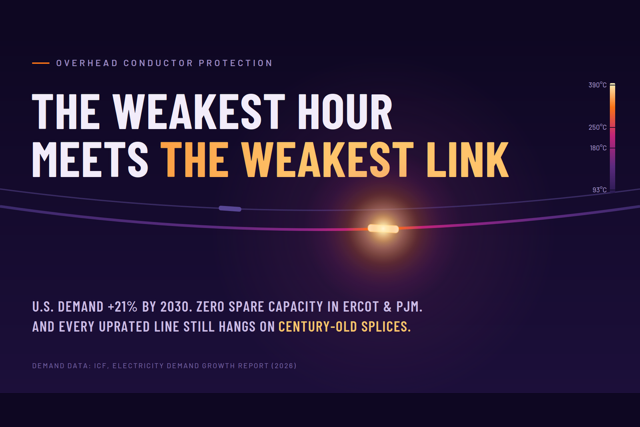
Total U.S. electricity demand will be up 21% by 2030 and 39% by 2035 from 2026 levels. Peak demand will be up 14% by 2030 and 25% by 2035. And against that growth, ICF counts roughly 26 GW of excess generating capacity nationwide above minimum reliability requirements: about 3% of the U.S. fleet. In ERCOT and PJM, the number is zero. Not “tight.” Zero. SERC and NYISO are forecast to follow within a few years.
Yes, a historic generation buildout is underway; ICF projects 445 GW of additions from 2026 through 2030. But read the fine print: only 68 GW arrives in 2026, and on a peak-contribution basis, those 445 GW deliver only about 191 GW of dependable capacity. Meanwhile, the loads are asking for service now.
So what does ICF prescribe for the gap years? Better use of what's already built. Grid-enhancing technologies. Higher utilization of existing corridors. Conditional firm service that connects new loads today using the grid's spare capacity, in exchange for curtailment during constrained hours. FERC Orders 881 and 1920 already point in the same direction.
The report's transmission section puts it in language worth pinning to the wall of every planning department. Transmission investment is rising steadily (roughly $178 billion planned by investor-owned utilities for 2025 through 2028, per EEI figures cited in the report), and ICF calls transmission the primary enabler of future load growth. Then comes the qualifier: how quickly that growth can be served will depend as much on optimizing the grid we already have as on completing the major projects. I agree with every word of it. And I want to talk about the assumption buried inside that qualifier, the one nobody at ICF, or FERC, or most utilities ever examines.
Every better-utilized line hangs on its connectors
When we say a transmission line will run at higher utilization, here is what we mean physically: more current, more of the time, through every component in the circuit. The conductor. The suspension hardware. And the connectors (splices and dead-ends).
The conductor gets all the attention. It has a thermal rating, a sag model, and sometimes a dynamic rating system watching it in real time. The connectors get none. They are assumed to be at least as good as the conductor they join.
That assumption is roughly 100 years old, and it is wrong.
The compression connector, the industry's default connector technology since the 1920s, depends on residual mechanical stress from the crimping operation to maintain its electrical interface. Published research tells us how little of that stress survives: after the compression die is removed, the connector retains only 5–18% of peak crimping stress. Thermal cycling then relaxes 92–95% of what remains. The degradation is internal, invisible from the ground, and cannot be remedied by any surface treatment or coating.
This is not a fringe concern. Consider where the standards stand: the published ANSI standard for transmission connectors, C119.4, covers connectors designed for normal operation at or below 93°C. C119.7, the standard intended to qualify connectors for high-temperature conductors, remains unpublished after years of committee work. The industry is deploying conductors rated to 250°C, governed by connector standards written for 93°C. That gap is the story.
Independent testing puts numbers on the gap. In thermal cycling performed at Kinectrics (report K-657046), a conventional compression splice failed at cycle 50. A ClampStar® shunt on the same program completed a total of 1,000 cycles, 500 at 335°C and 500 at 390°C without degradation.
Thin margins make the contingency case real
Here's where ICF's reserve-margin math connects directly to hardware. A grid with a 3% national cushion and zero in its two largest markets is a grid where N-1 contingency events stop being planning abstractions and become operating reality.
Consider two parallel lines sharing a corridor, a configuration found across every RTO. When one trips, the survivor picks up the load, roughly doubling the current it carries. Because heating scales with the square of current, doubling the current quadruples the I²R heating at every connector, driving the conductor toward its maximum rated temperature (250°C for ACSS). To be precise, utilities don't operate anywhere near that temperature continuously, and shouldn't. But the contingency case is exactly what qualifies the hardware. Connectors on both parallel lines must be rated for the full temperature the conductor can reach under N-1, because on the day one line is lost, the other line's splices are all that stand between a contingency and a cascading outage.
A compression connector that has quietly relaxed through twenty years of thermal cycles meets that emergency condition at the worst possible moment.
The weakest hour, the weakest component
One of the report's sharpest lines comes from its demand-response analysis: “reliability depends on the weakest hour, not the best hour.” ICF wrote it about customer programs, and it's exactly right. A resource that delivers early in an event but fades before it ends is not dependable capacity.
The same logic governs hardware. Reliability depends on the weakest component, and on a heavily utilized transmission line, the weakest component is seldom the conductor. It's the connector: unmonitored, unrated for the duty it's being asked to perform, and degrading in a way no inspection from the ground can see.
Some utilities have quietly reached this conclusion already. At least one major utility's publicly filed wildfire mitigation plan includes a dedicated, ongoing splice-shunting program as a named risk-reduction activity: a formal acknowledgment, in a regulatory document, that legacy splices are a fire and reliability risk worthy of systematic remediation.
What connector readiness looks like
If your system is on ICF's map of high-growth, low-headroom regions, the question to put to your standards and asset-management teams is simple: when this line runs hotter, what is the rated temperature of every splice and dead-end on it, and how do we know?
For circuits where the honest answer is "we don't," ClampStar® Engineered Electrical/Mechanical Shunts offer a path that doesn't require cutting the conductor or taking the extended outages of full splice replacement. A ClampStar unit installs over the existing connector, restoring full mechanical strength and providing a parallel electrical path independently verified through 1,000 thermal cycles at temperatures well beyond the 250°C rating of ACSS, qualifying the connection for the duty the next decade will actually demand of it.
ICF has told us where the demand is going and why the grid will be asked to do more with the lines it already has. The conductor community has spent a decade preparing for that future. The connector question is the one still sitting unexamined in the middle of every uprated span.
It's worth asking before the weakest hour finds the weakest link.
Click here to access a link to a downloadable print-ready version of this article.
The Great Grid Illusion: Are We Overpaying for Transmission Conductors?
As the nation races to modernize its aging power grid, utilities are spending billions of dollars on massive infrastructure upgrades. Because these investments are folded into consumer electricity rates for the next 50 years or more, spending this money prudently is critical. But a debate is emerging over the very conductors that carry our electricity—and balancing promotional claims against engineering realities across different applications is essential.
On one side, we have traditional steel-core conductors, the long-standing workhorses of the grid. On the other hand, "polymer composite core" conductors are increasingly being adopted as a modern, high-tech solution. While these higher-priced composite conductors offer unique benefits, evaluating their cost-effectiveness across all scenarios requires objective scrutiny. According to a recent engineering assessment by Springer Power Consulting, some of the broader claims surrounding composite cores in certain cases warrant closer examination.
Click to read the rest of this T&D World Magazine article.

Unlocking 275 GW of Grid Capacity: The Hidden Hardware Risk of FERC 881
Unlocking 275 GW of Grid Capacity:
The Hidden Hardware Risk of FERC 881
We applaud organizations like FERC, PJM, and MISO for their proactive efforts to maximize our existing power grid. The recent push for Grid-Enhancing Technologies (GETs), Dynamic Line Ratings (DLRs), and the implementation of FERC Order 881 for ambient-adjusted transmission ratings are essential steps forward.
Combined with the DOE's recent $1.9 billion SPARK funding initiative and the NERC 2025 Long-Term Reliability Assessment's urgent call to bridge the "capacity gap," it is clear we must unlock capacity on our existing rights-of-way.
However, as we champion these ampacity-increasing programs, we must address a critical technical vulnerability and a widely misunderstood limitation: the N-1 contingency.
Driving increased ampacity rates on existing transmission lines means pushing significantly higher current flows through aging infrastructure. When you combine this with strict N-1 contingency requirements, where the grid must instantly absorb rerouted power from a failed companion circuit, these lines are forced to carry loads they have rarely, if ever, experienced.
The N-1 Reality Check: Why 180°C Isn't Enough
Under N-1 reliability standards, transmission lines must maintain reserve capacity to instantly absorb the load of a failed shared line. Because conductor temperature rises non-linearly with current, calculating this reserve isn't straightforward. Factoring in Dynamic Line Rating (DLR) variables, such as wind, solar absorptivity, and also conductor construction, further complicates the math. As a result, the 85°C and 120°C figures used in the subsequent analysis are practical illustrations, not exact calculations.
For example, if you are looking at lines with a maximum rating of 180°C, N-1 dictates that their continuous, everyday usable capacity is severely throttled back, often hovering around just 85°C.
On the other hand, advanced lines, such as ACSS/TW rated for 250°C, can comfortably operate continuously around 120°C. When the industry hears about new technologies pushing 180°C, it sounds perfectly reasonable on the surface. But without factoring in the severe N-1 penalty, operators are caught off guard when their usable capacity drops drastically, leading straight to grid congestion and skyrocketing congestion rents. To put the cost of congestion rents into perspective, U.S. utilities spent upward of $8.3 billion on them in 2024.
The Immediate Danger to Physical Hardware
Even if you have lines capable of operating at 250°C, legacy connectors, including splices, deadends, and suspension clamps, are typically only rated for 100°C to 125°C. When an N-1 event pushes that 120°C continuous load up toward the 250°C limit, the risk of catastrophic connector failure and subsequent line drops increases significantly.
The Push for New Standards
The industry is already working to mitigate these thermal challenges, with rigorous, ongoing tests at NEETRAC (National Electric Energy Testing, Research and Applications Center) and EPRI (Electric Power Research Institute) to develop the new ANSI C119.7 standard for high-temperature, high-stress conditions. But to safely realize the benefits of FERC Order 881 today, grid modernization policy must account for the physical limits of our existing hardware.
The Solution: Engineered Electrical / Mechanical Shunts
The most logical, rapid, and highly reliable solution for these anticipated thermal problems is the installation of engineered electrical/mechanical shunts, such as ClampStar®. These shunts permanently bypass aging and degrading connections, creating a parallel electrical path of lower resistance that carries the load around the limiting connector and keeps the original hardware cool.
Crucially, because they safely increase the power-carrying capacity and efficiency of existing transmission lines, ClampStar engineered electrical/mechanical shunts directly meet the definition of a Grid-Enhancing Technology (GET). By resolving thermal bottlenecks and maximizing the usable ampacity of the current infrastructure, they serve as a vital, hardware-based GET that enables the grid to handle more power without the cost or delay of full reconductoring.
Consider the immediate impact of deploying this technology:
Unlocking 275 GW of Latent Capacity: By upgrading the roughly 30,000 circuit miles of artificially throttled ACSS on the U.S. grid with engineered shunts, we can instantly unlock an estimated 275 GW of latent power capacity, without pulling a single foot of new conductor. This is based on an analysis of 2,920 circuit miles, which represents 10% of the total existing ACSS conductor.
Massive Economic Benefits: By relieving grid congestion and avoiding exorbitant congestion rents, this technology can generate an estimated $48 billion in annual revenue increases.
The Ultimate Thermal Headroom: While ClampStar units are engineered and tested to survive temperatures up to 390°C, we know operators aren't running lines at that temperature daily. The real value is the thermal headroom. It ensures that when an N-1 event forces your 250°C rated lines to spike to their absolute limit, the connectors won't be the weak link that brings the grid down. ClampStar runs up to 126.3°C cooler than the conductor itself.
Flawless Reliability: With over 18 years of global deployment and several hundred thousand units installed, ClampStar has a flawless track record with no known failures.
We cannot squeeze more power out of our existing grid without first ensuring the hardware holding it together won't succumb to thermal runaway. Engineered shunting and connector reinforcement must be included in standard grid optimization strategies; it is the fastest, most cost-effective path to safely powering our digital economy.
Call 800-269-1462 today to schedule a technical briefing on maximizing your N-1 operating capacity.
Click here to access a link to a downloadable print-ready version of this article.

Strategic Implementation of Grid-Enhancing Technologies (GETs) to Unlock Latent Capacity in Your Network
Executive Summary
Your transmission network faces a critical challenge: high-performance assets are currently constrained by legacy hardware. As local demands for electrification and data center load growth accelerate, electric utilities must prioritize solutions that maximize the value of existing rights-of-way.
By deploying ClampStar® units across your existing Aluminum Conductor Steel Supported (ACSS) lines, your network can unlock substantial latent power capacity immediately. This document validates how addressing specific hardware bottlenecks can secure grid reliability for your customers using a time-tested, industry-proven solution.
1. The Primary Bottleneck: Why Connectors Dictate Your Capacity
While your ACSS conductors are engineered for high-temperature operation (maintaining tensile strength at 250°C), your network’s actual ampacity is likely capped by the thermal limitations of connectors (splices, suspension clamps, and deadends), which are typically rated for only 100°C to 125°C.
This mismatch leaves valuable capacity stranded on your lines; the conductor can handle the increased load your customers need, but the legacy hardware cannot.
2. A Systematic Approach to Local Constraints
We recognize that your transmission circuits are complex systems with many limiting elements, such as substation transformers and switches. Historically, uprating studies may have overlooked connectors because they were the most severe bottleneck.
By deploying ClampStar to permanently resolve this primary bottleneck on your lines, we enable your engineering team to shift its focus. Once the thermal restrictions of line splices and clamps are removed, you can systematically address secondary constraints at the substation level. ClampStar clears the path for a holistic review, allowing you to fully utilize the potential of your specific infrastructure.
3. Proven Reliability for Your Ratepayers
Unlike experimental technologies that introduce new risks to your grid, ClampStar is a mature solution with a track record of stability. First introduced in 2008 and deployed globally for over 18 years, with hundreds of thousands of units installed and zero reported failures, it offers the operational certainty required for your critical infrastructure decisions.
4. Engineering Validation: Protecting Your Specific Assets
The ClampStar assembly is engineered to function reliably for the entire remaining life of the conductor it protects.
- Cooler Operation: Empirical Class AA testing confirms ClampStar units operate significantly cooler than the conductor itself (documented at 126.3°C cooler than control conductors in transmission applications).
- Safety Margin: Because the unit operates well below the conductor’s thermal limit, even during catastrophic overload events, it eliminates the risk of thermal degradation on your lines.
5. Immediate Value for Your Service Area
Regulatory bodies and industry leaders are pushing for Grid Enhancing Technologies (GETs) to extract value without the delays of new construction. ClampStar allows [Local Utility Name] to uprate lines from ~100°C to 250°C+ without the need for new towers, difficult permitting processes, or expanded rights-of-way. This effectively doubles the usable ampacity of your existing brownfield assets.
Conclusion
You already possess the conductor capacity to meet growing local demand; you simply lack the connectivity to utilize it. Installing ClampStar is a scientifically validated method to bridge this gap for your network. It transforms your thermally limited lines into high-capacity assets, delivering the speed, safety, and reliability your community expects.
Click here to access a link to a downloadable print-ready version of this article.

Addressing Escalating Circuit Failure: A Proactive Approach
Electrical connectors, fundamental components of any power distribution system, are subject to inevitable aging and degradation. The only exception to this is a thermal-fusion weld, which effectively eliminates the electrical interface by creating a homogenous connection. The effective electrical interface, responsible for current transmission, represents a fraction of the apparent interface, typically ranging from 1.5% to 7% of the surface area. The discrete contact points facilitating current flow are known as “a-spots,” with the remaining surface areas rendered ineffective due to factors such as chemical reactions and corrosion, most notably the formation of aluminum oxide, a potent electrical insulator.
Connectors are engineered with materials and methodologies to mitigate these chemical effects and maximize the percentage of functional a-spots. However, a natural chemical aging process occurs, leading to corrosion and subsequent separation of the a-spots. This process is accelerated by thermal energy; elevated temperatures directly correlate with an increased rate of electrical interface degradation.
To evaluate connector performance, a metric known as the “k factor” is employed. It's a comparison of how much resistance the connector has compared to the wire it's connected to. Ideally, you want this k factor to be less than 1:1. When it exceeds that, especially hitting the point where the connector's temperature matches the conductor's, things are considered "failed" by industry standards. Even if it's slightly above 1:1, the connector might still seem okay because it can get rid of heat better than the wire, but that won't last. Eventually, it'll just overheat and go into "thermal runaway."
Empirical data suggests a typical service life of 40-70 years for utility-class overhead connectors; however, this is contingent upon the quality of workmanship during installation. Suboptimal installation practices lead to premature failure. Additionally, operational temperatures significantly impact connector lifespan. Originally designed for applications with conductors not exceeding 75°C, connectors are now frequently exposed to higher temperatures due to increased grid demand, accelerating the aging process.
To address these challenges without resorting to complete system replacement, Engineered Electrical-Mechanical Shunts with the trade name ClampStar® provide a robust solution. ClampStars are not merely a temporary fix but offer superior performance compared to original connectors, particularly in aged and weathered conductor environments. Designed specifically for such conditions, ClampStars restore mechanical integrity and significantly increase current capacity, well above the original connectors when newly installed.
ClampStars are designed to withstand high temperatures, undergoing testing at significantly elevated levels, and are proven to maintain resistance stability during extended thermal cycling. When compared to traditional, non-shunted splices via infrared thermography, ClampStars demonstrate superior thermal performance and reliability, particularly in aged conductor scenarios.
With installation times of approximately 4 minutes on the smallest units for distribution size conductors to 8-10 minutes for transmission class units for the largest conductors, ClampStar installations are efficient and require minimal tooling, typically an impact driver and a wire brush. Pre-loaded with a proprietary high-temperature inhibitor known as CC² (pronounced as CC Squared) allowing their use on 250°C conductors, and equipped with torque-limiting fasteners, ClampStars are readily deployed on energized conductors, minimizing downtime.
In conclusion, utilizing ClampStars for overhead splices, deadends, and suspension clamps represents an efficient, cost-effective, and technically sound approach to extending the life of aging electrical systems, enhancing performance, and meeting ever-evolving energy demands. This strategy offers a prudent alternative to large-scale replacements while ensuring reliable power delivery.
ClampStars offer a simple, rapid, and cost-effective way to fully restore mechanical and electrical integrity, meeting today's growing demands. It's a smarter way to keep the lights on without breaking the bank.

Wildfire Mitigation Benefits of ClampStar Engineered Electrical/Mechanical Shunts
As wildfire seasons become increasingly severe, the need for robust wildfire mitigation strategies has never been more critical. The risks posed by electrical systems operating in overgrown, dry environments are substantial, making effective management essential for asset managers, operations, and maintenance personnel. One promising solution lies in the innovative design of ClampStar® engineered electrical/mechanical shunts, which provide a vital layer of protection through their reinforcement capabilities of suspension clamps, deadends, and splices, both compression and automatic.
A Preemptive Approach to Safety
Wildfires can stem from the simplest of failures within electrical infrastructure — from poor installation practices to corroded connections. The installation of ClampStars effectively serves as a proactive approach against such catastrophic incidents while delivering peace of mind, similar to an insurance policy but without having to pay annual premiums. By reducing electrical resistance thereby eliminating high-temperature connections, these shunts enhance system resilience and reduce the likelihood of arcs and ground faults that can ignite wildfires.
Notably, overhead splice shunts are determined to be the #3 method for wildfire risk activity effectiveness. Only Public Safety Power Shutoffs (PSPS) and undergrounding electric lines have a higher effectiveness rating.
Versatile Applications
ClampStars are engineered to function optimally across various electrical configurations, including suspension clamps, deadends, compression splices, and automatic splices. Clampstar’s capacity to reinforce electrical and mechanical connections helps extend the life of conductors and components, which in turn increases the lifespan of the entire system while minimizing failure points. Due to ClampStar's 390℃ rating, these shunts ensure reliable electrical connectivity, maintaining a balanced system even under increased loads.
Compression splices benefit from ClampStars by enhancing the mechanical integrity of joints, ensuring that there are no loose connections that could lead to elevated temperatures and eventual ignition. Automatic splices are particularly challenging due to their evolving operational conditions, yet integrating ClampStars provides an additional layer of thermal stability and conductivity, ensuring that even in the event of fault occurrence, the resulting heat is rapidly dissipated.
Budget-Friendly Solutions
For asset managers, the upfront investment in ClampStar technology can often be categorized as a capital expense, depending on an organization's specific accounting policies and regulatory guidelines, because it is an upgrade and life extension of existing assets. This classification allows for budgeting flexibility that aligns with long-term organizational goals. Given its potential for reducing liability and protecting against devastating infrastructure failures, the return on investment is notably strong when considering the catastrophic costs associated with wildfire incidents and the subsequent loss of infrastructure.
Engineering Excellence Meets Practicality
From a technical perspective, the design of ClampStars boasts advanced material science and engineering principles aimed at high performance in adverse conditions. The dual-action design leverages both electrical and mechanical properties to ensure that every connection maintains peak operational efficiency, thus reducing service interruptions and enhancing overall system reliability.
Moreover, ClampStar technology undergoes rigorous testing to ensure compliance with industry standards, resulting in a platform that not only supports the operational needs of linemen and engineers but also exceeds the specific safety requirements set forth by regulatory bodies.
Conclusion
The adoption of ClampStar engineered electrical/mechanical shunts represents a forward-thinking approach to wildfire mitigation within electrical systems. By enhancing the reliability of suspension clamps, splices, and deadends, and ensuring heightened safety standards, ClampStars serve as a critical enhancement to today’s electrical infrastructure. As organizations prioritize the prevention of catastrophic incidents, this innovative solution not only safeguards assets but also contributes to a sustainable operational environment, ensuring that the risks associated with electrical infrastructure are managed effectively for years to come.


