 Proudly Made in the USA
  800.269.1462

How To Properly Repair Damaged Conductor Caused By Spacer Dampers
Spacer dampers, designed to provide proper damping of wind-induced vibrations for bundled conductor lines, have been around for more than 50 years and like most hardware exposed to the elements, needs to be replaced at some point in time. Most often, replacing old spacer dampers is as easy as swapping out the old unit for a new one. Unfortunately, however, there will be instances where removing the old spacer damper reveals damaged conductor underneath which must be properly corrected.
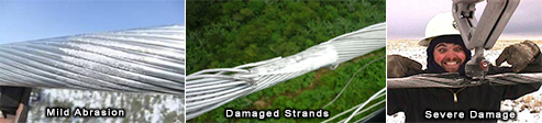
As seen in the photos below, spacer dampers can create varying degrees of conductor damage grouped into 3 categories; mild abrasion, damaged strands and severely damaged strands.
Repairing conductor with damaged and/or severed strands requires a process that restores full tension and ampacity to the conductor and the best method to accomplish this is an engineered mechanical shunt.
Our CRU series (Conductor Repair Unit) is the safest and quickest permanent system to restore 100% electrical and mechanical properties to damaged conductors, on energized lines at any voltage while avoiding the need for a service interruption. As with all of our products, this unit will install in only 6-8 minutes, which obviously decreases lineman safety risk.
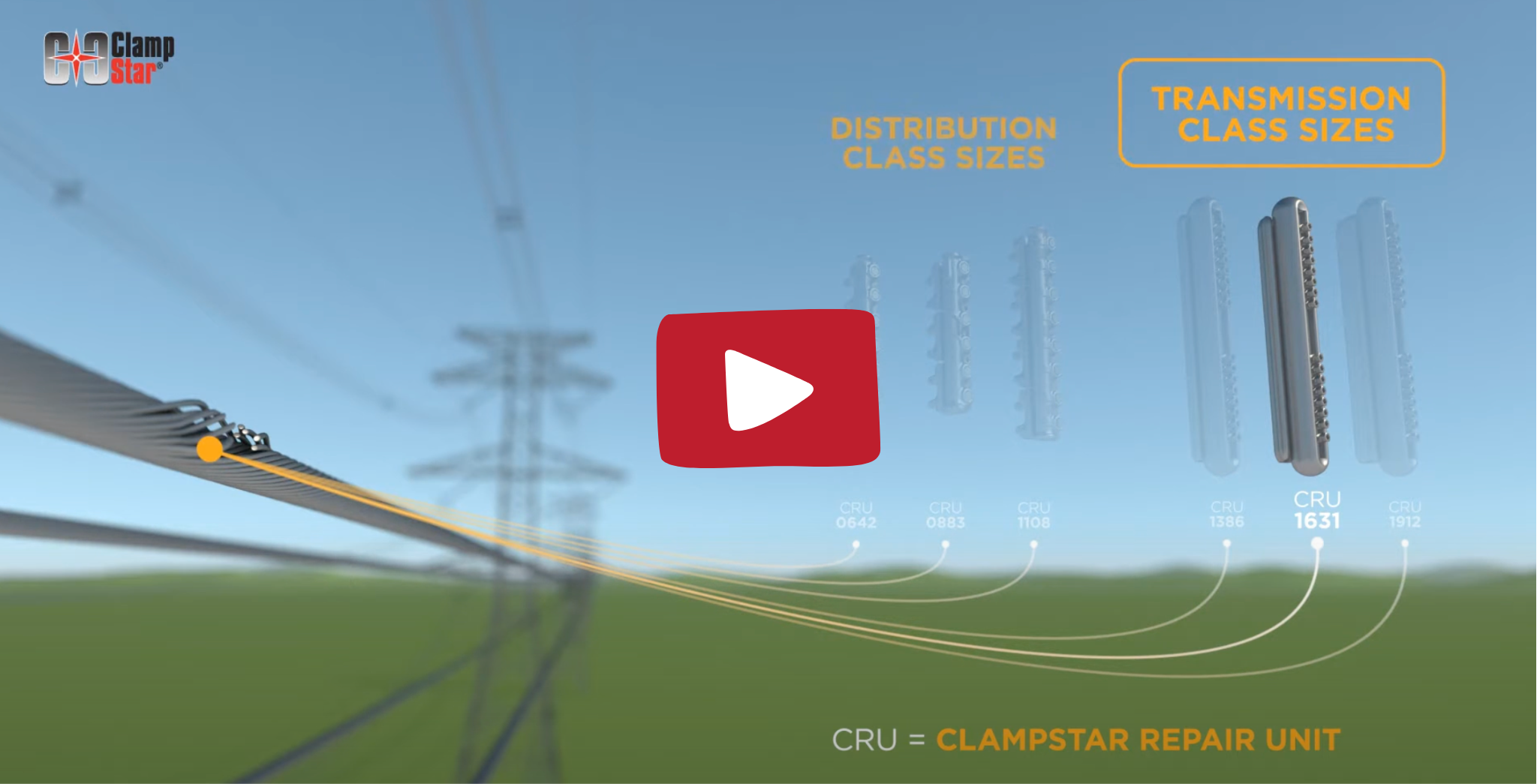
Available Conductor Repair Units


With corona free design and our patented “Constant Clamp Force System”, transmission class CRU ClampStar® units designed to accommodate conductors sized from 447 kcmil – 2515 kcmil allows carts to easily cross over (see image below). Full tension is achieved with these ClampStar devices if the conductor core is intact, which is likely the case with spacer-damper replacement.
Watch this video below to learn the best method for repairing damaged overhead
Distribution class conductors –>
Smaller diameter conductors utilize a different style ClampStar® that can be seen by clicking here.
ClampStar units are also available for the repair of overhead splices, dead ends, OHSW and OPGW.